Difference between revisions of "Current driver:Current driver"
| Line 11: | Line 11: | ||
[[File:schematic 8ch driver.png|left|500px|800px|alt=A large clock tower and other buildings line a great river.]] | [[File:schematic 8ch driver.png|left|500px|800px|alt=A large clock tower and other buildings line a great river.]] | ||
| − | [[File:schematic 8ch driver.png|right|thumbnail|alt= | + | [[File:schematic 8ch driver.png|right|700px|thumbnail|alt=Schematic for current feedback control loop topology showing 0.2 ohm current sense resistor and OPA549 power op amps in push-pull configuration]] |
[[File:schematic 8ch driver.png|left|800px |1000px|link=Main Page |alt=Alt |Schematic for current feedback control loop topology showing OPA549 power op amps in push-pull configuration.]] | [[File:schematic 8ch driver.png|left|800px |1000px|link=Main Page |alt=Alt |Schematic for current feedback control loop topology showing OPA549 power op amps in push-pull configuration.]] | ||
Revision as of 13:33, 15 February 2016
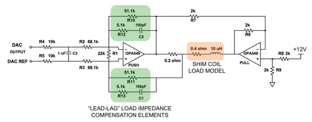
In collaboration with Jacob White and Nick Arango at MIT, we have developed a low-cost 8-channel digitally-programmable current driver that can supply up to 8 amps DC per channel (up to 60 volt output). The board is intended as a scalable solution for supplying current to matrix shim coil arrays that require an independent, dynamically-switchable current driver for each shim coil element. Cost per channel is ~$75. The circuit uses a simple feedback control topology built around OPA549 linear power stage op amps in a push-pull configuration. The voltage across a current sense resistor is sensed in the feedback topology to allow control of the actual current output to the load. The resistors and capacitors in the feedback loops can be adjusted to ensure stability for driving a particular load impedance. With the component values used in the board files (see below), the feedback loop compensation elements is set up to compensate a 10 uH reactive load. The design retains sufficient gain in the audio frequency range to reject disturbances caused by gradient coil switching in the MRI scanner environment. The end result is a stable output current (>45 deg phase margin) with ~50us rise time and very good disturbance rejection for maintaining stable shim currents during MR acquisitions. The outputs of each channel can be tied together to increase the current beyond 8 amps. For most loads, heat sinking the OPA549s is required since most of the voltage drop (and heat dissipation) will occur inside these ICs.
An 8-channel 16-bit DAC is used to update the current setting on each channel. The current sense resistor voltage drop is buffered and sent to an ADC so that the output current on each channel can be monitored by computer. Presently the board is controlled using a Raspberry Pi device with a T-cobbler breakout board.

![]()
Click here to download Eagle board file and schematic as well as GERBER files for board fabrication.
Known bugs for Eagle board Rev. A (V4):
- Bias voltage (+5V) was mistakenly not provided to the IC that buffers the 2V reference voltage that is output from the DAC. A jumper wire must be used to supply this bias to the IC. It is located physically next to the LTC2656 DAC.