Difference between revisions of "Current driver:Current driver"
| Line 10: | Line 10: | ||
| − | [[Image:shim supply 8ch photo.png| | + | [[Image:shim supply 8ch photo.png|400px |link=Main Page |alt=Alt text |8ch current driver board with key components highlighted.]] |
'''Known bugs for board Rev A (V4):''' | '''Known bugs for board Rev A (V4):''' | ||
* Bias voltage (+5V) was not provided to the LVM331 IC that buffers the 2V reference voltage that is output from the DAC. A jumper wire must be used to supply this bias to the IC. | * Bias voltage (+5V) was not provided to the LVM331 IC that buffers the 2V reference voltage that is output from the DAC. A jumper wire must be used to supply this bias to the IC. | ||
Revision as of 13:00, 18 January 2016
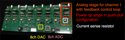
In collaboration with Jacob White and Nick Arango at MIT, we have developed a low-cost 8-channel digitally-programmable current driver that can supply up to 8 amps DC per channel (up to 60 volt output). The board was developed as a scalable solution for matrix shimming applications that require an independent current driver for each shim coil in the array. Cost per channel is ~$75. The circuit uses a simple feedback control topology built around OPA549 linear power stage op amps in a push-pull configuration. The voltage across a current sense resistor is sensed in the feedback topology to allow control of the actual current output to the load. The resistors and capacitors in the feedback loops can be adjusted to ensure stability for driving a particular load impedance. As specified in the board files below, the feedback loop compensation elements is set up to compensate a 10 uH reactive load. The design retains sufficient gain in the audio frequency range to reject disturbances caused by gradient coil switching in the MRI scanner environment. The end result is a stable output current (>45 deg phase margin) with ~50us rise time and very good disturbance rejection for maintaining stable shim currents during MR acquisitions.
An 8-channel 16-bit DAC is used to update the current setting on each channel. The current sense resistor voltage drop is buffered and sent to an ADC so that the output current on each channel can be monitored by computer. Presently the board is controlled using a Raspberry Pi device with a t-cobbler breakout board.
Click here to download Eagle board file and schematic as well as GERBER files for board fabrication.
Known bugs for board Rev A (V4):
- Bias voltage (+5V) was not provided to the LVM331 IC that buffers the 2V reference voltage that is output from the DAC. A jumper wire must be used to supply this bias to the IC.